adsense 1

Saturday 5 March 2016

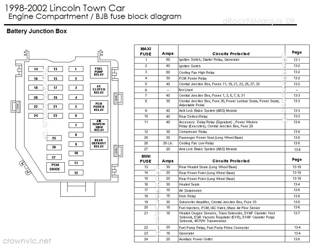
Lincoln town car engine fuse box diagram

Lincoln town car engine fuse box diagram

BJB FUSE BOX DIAGRAM LINCOLN 1998 - 2002


2006 TRIUMPH SPEED III FUSE BOX DIAGRAM

TRIUMPH SPEED III FUSE BOX DIAGRAM


06 Triumph Speed III Fuse Box Diagram


06 Triumph Speed III Fuse Box Map

Fuse Panel Layout Diagram Parts: starter relay, headlight relay, engine management system relay, direction indicator unit, cooling fan relay, fuel pump relay.


1997 SAAB 900 S FUSE BOX DIAGRAM

1997 SAAB 900 S FUSE BOX DIAGRAM


1997 Saab 900 S Fuse Box Diagram


1997 Saab 900 S Fuse Box Map
Fuse Panel Layout Diagram Parts: fog light disconnection, reversing light, shift lock relay, intermittent wiper operation relay, rear window, ignition switch, intermittent windscreen wiper operation, heated rear window, fuel pump relay, washer fluid pump, starter relay, main relay, electrically heated rear seat.


2005 MAZDA TRIBUTE FUSE BOX DIAGRAM

2005 MAZDA TRIBUTE FUSE BOX DIAGRAM


2005 Mazda Tribute Fuse Box Diagram


2005 Mazda Tribute Fuse Box Map
Fuse Panel Layout Diagram Parts: trailer tow park lamp, ignition switch, powertrain control module, fuel pump relay, main fan relay, high mounted stop lamp, powertrain control module, antilock brake system, speed control, brake pedal position, instrumentr cluster, diagnostic connector, power mirror, power door lock, power seat, hazard mirror, sunroof, power window, low beam relay, cigar lighter, deactivetor switch, transmission shift lock, brake, air bag, passenger airbag deactivation, heated seat module, start relay, park lamp relay, rear defrost relay, accessory delay relay.


2004 FORD F 250 FUSE BOX DIAGRAM

2004 FORD F 250 FUSE BOX DIAGRAM


2004 Ford F 250 Fuse Box Diagram


2004 Ford F 250 Fuse Box Map

Fuse Panel Layout Diagram Parts: blower relay, door lock switch, multifunction switch, ABS system, trailer tow package, electronic engine control, main light switch, headlamp, auxiliary power pocket, daytime running lamp, air bag diagnostic, trailer back up lamp, trailer running lamp relay, windshield wiper/washer relay, trailer battery charge relay, power seat control switch, park lamp relay, customer access, trailer electronic brake controller, radio, trailer battery charge relay, fuel pump relay, ignition switch, junction box fuse relay.

2002 KIA SPORTAGE MAIN RELAY FUSE BOX DIAGRAM

2002 KIA SPORTAGE MAIN RELAY FUSE BOX DIAGRAM


2002 KIA Sportage Main Relay Fuse Box Diagram


2002 KIA Sportage Main Relay Fuse Box Map

Fuse Panel Layout Diagram Parts: ignition switch, power window, fuel pump, injector main relay, fuel pump relay, anti lock brake system, headlight, fuel injection system, A/C condenser fan, for protection of all circuit, brake light, license plate light, dome light, hazard light.


1994 ISUZU TROOPER MAIN FUSE BOX DIAGRAM

1994 ISUZU TROOPER MAIN FUSE BOX DIAGRAM


1994 Isuzu Trooper Main Fuse Box Diagram


1994 Isuzu Trooper Main Fuse Box Map

Fuse Panel Layout Diagram Parts: fog light, engine control, anti theft system, horn, headlight and fog light, headlight, hazard light, anti lock brake system, engine control taillight.


1999 BMW Z3 ROADSTER ENGINE FUSE BOX DIAGRAM

1999 BMW Z3 ROADSTER ENGINE FUSE BOX DIAGRAM


1999 BMW Z3 Roadster  Engine Fuse Box Diagram

1999 BMW Z3 Roadster Engine Fuse Box Map
1999 BMW Z3 Roadster  Engine Fuse Box Map
Fuse Panel Layout Diagram Parts: hazard warning light, power window, wiper, tail light, engine, meter, heater motor, stop lamp.


2001 CHEVY TRACKER UNDER THE DASH FUSE BOX DIAGRAM

2001 CHEVY TRACKER UNDER THE DASH FUSE BOX DIAGRAM


2001 Chevy Tracker Under The Dash Fuse Box Diagram


2001 Chevy Tracker Under The Dash Fuse Box Map


Fuse Panel Layout Diagram Parts: turn signal, back up light, windshield wiper, rear window wiper/washer, Oxygen sensor heater, cruise control, door lock, brake light, horn, center high-mounted stop lamp, ignition coil, meter, G sensor, power mirror, power window, dome light, license plate light, marker light, instrument panel illumination, hazard light, rear window defogger, daytime running lamp.


1999 CHEVY TRACKER LAYOUT FUSE BOX DIAGRAM

1999 CHEVY TRACKER LAYOUT FUSE BOX DIAGRAM


1999 Chevy Tracker Layout Fuse Box Diagram


1999 Chevy Tracker Layout Fuse Box Map

Fuse Panel Layout Diagram Parts: power window, dome light, license plate light, marker light, instrument panel illumination, hazard light, sensor heater, cruise control, ignition coil, meter, cigar lighter, radio, power mirror, door lock, brake light, horn, stop lamp, rear window defogger, daytime running lamp, turn signal, back up light, windshield wiper/washer, rear window wiper/washer.


2007 OLDSMOBILE INTRIGUE REAR FUSE BOX DIAGRAM

2007 OLDSMOBILE INTRIGUE REAR FUSE BOX DIAGRAM


2007 Oldsmobile Intrigue Rear Fuse Box Diagram


2007 Oldsmobile Intrigue Rear Fuse Box Map
Fuse Panel Layout Diagram Parts: cigar lighter, crank signal ECU cluster, cluster PCM, low blower, HVAC, cruise control, turn signal, air bag, instrument cluster, CD changer, blower, hazard lamp, stop lamp, door lock, power mirror, park lamps, tail lamps, panel dimming, wiper, radio, cruise control, daytime running lamp, radio, data link, ABS system.


94 JEEP GRAND CHEROKEE SE FUSE BOX DIAGRAM

94 JEEP GRAND CHEROKEE SE FUSE BOX DIAGRAM

fuse box 


94 Jeep Grand Cherokee SE Fuse Box Diagram


94 Jeep Grand Cherokee SE Fuse Box Map
Fuse Panel Layout Diagram Parts: power antenna, trailer tow relay, stop lamp, hazard lamp, security lamp, courtesy lamp, security alarm module, fuse battery, radio accessory, cigar lighter, park lamp, horn lamp, power door lock, ABS module, turn signal flasher, hevac module, air bag module, converence item, hazard rear window, courtesy lamp, air bag module, power mirror, power seat, power window, windshield wiper, heated rear window.


1992 MERCEDES BENZ E190 FUSE BOX DIAGRAM

1992 MERCEDES BENZ E190 FUSE BOX DIAGRAM


1992 Mercedes Benz E190 Fuse Box Diagram


1992 Mercedes Benz E190 Fuse Box Map

Fuse Panel Layout Diagram Parts: auxiliary fan, high speed relay, power seat relay, combination relay, rear defogger, timer, washer, wiper, hazard, signal, power window, auxiliary fuse, holder, power seat.


1997 MERCURY MYSTIQUE FUSE BOX DIAGRAM

1997 MERCURY MYSTIQUE FUSE BOX DIAGRAM


1997 Mercury Mystique Fuse Box Diagram


1997 Mercury Mystique Fuse Box Map

Fuse Panel Layout Diagram Parts: cooling fan relay, fuel pump relay, PCM power relay, horn relay, starter relay, low beam headlamp relay, A/C wide open throttle relay, high speed engine, cooling fan relay, daytime running lamp, A/C clutch relay, low speed engine.


2001 FORD F250 UNDER HOOD FUSE BOX DIAGRAM

2001 FORD F250 UNDER HOOD FUSE BOX DIAGRAM


2001 Ford F250 Under Hood Fuse Box Diagram

2001 Ford F250 Under Hood Fuse Box Map
Fuse Panel Layout Diagram Parts: ABS system, trailer tow package, air bag diagnostic, power seat control switch, trailer electronic brake controller, radio, trailer battery charge relay, electronic engine control, fuel pump relay, ignition switch, junction box fuse relay, blower relay, door lock switch, trailer back up lamp, trailer running lamp relay, windshield wiper/washer relay, trailer battery charge relay, park lamp relay, customer access, main light switch, headlamp, auxiliary power pocket, daytime running lamp, multi-function switch.

WIRING DIAGRAMS OF 1962 FORD V8 GALAXIE

WIRING DIAGRAMS OF 1962 FORD V8 GALAXIE


Now, let us take you to see this schematic about the wiring diagrams of a 1961 Ford V8 Galaxie. Be sure to have read about the schematic comprehensively before you do any wiring work on your Ford car wiring systems. The parts inside will be such follows: left direction indicator, right direction indicator, light switch, ignition switch, gas gauge, instrument light, gauge voltage regulator, etc. 


DIY SURGE PROTECTOR CIRCUITS

DIY SURGE PROTECTOR CIRCUITS

When has a thunderstorm. Electrical is off, or power surges the extreme, but sometimes we need to use the electrical appliances. And in sensitive electrical appliance damaged easily. Power surges a little. Might make it wastes. In particular surge. At you firstly turn on the switch. Should have the power to delay, gradually release it into these appliance. I would like to introduce the concept of a two ac delay circuits. Which both two circuit is designed in easily ideals for all people.

PROTECTION SURGE WITH DELAY THE RELAY USING IC 4011

This circuit can be used to delay other appliances connected to the output of the relay. After working set To prevent equipment damage from pressure.
Surge.
The IC number is 4011 Nand Gate CMOS .When switch S1 is current through R1. To charge at C1.This takes time to fully charge, and when a voltage input
Pin 1 and pin 2 of IC1.The output from pin 3 through a logic “0″ Volts to the control relay contacts to control the relay to work editing equipment, external works.That the time delay relay set from T = R1 x C1 x 0.85 is measured in seconds.

DELAY TO SUPPLY VOLTAGE FOR SURGE PROTECTOR BY SCR

Power source that, when connected to an external circuit, and now will turn to a current surge.Power supply is a high voltage surges.External circuit therefore damage.Which can solve this problem with the delay to a power source.When supply switches.Delay circuit to work, the delay occurred during the current surge.Then connected to a power source as usual.
Operation of the circuit be When a power supply to the Supply voltage in.Delay circuit will start by Delay depending on the charge of C1 is growing.
So take some time to be full.When C1 is fully charged will allow the current to flow through ZD1 zener diode 6 volt.This will limit the voltage at the trigger pin to G (gate) of the SCR.The aforesaid conduct of the SCR Supply voltage to output Delayed supply out.


SIMPLE FM RADIO RECEIVER

SIMPLE FM RADIO RECEIVER


This FM radio receiver circuit is very simple to build and is powered by just a single 1.5V battery cell. Receiver consists of a regenerative rf stage, TR1, followed by a two of three-stage audio amplifier, TR2 to TR4. In some areas 3 stages of audio amplification may not be necessary, in which case TR3 and its associated components can be omitted and the free end of capacitor C5 connected to the collector of TR2.

The critical part of the fm radio receiver is the first stage, TR1/VC1, where the wirings must be kept as short as possible. Coil L1 is formed by winding 8 turns of 1mm (20 swg) enamelled copper wire on a 6 mm diameter former, which is then removed. After that L1 should be stretched carefully and evenly to a length of about 13mm.

The tunning capacitor VC1 is one of the two fm sections of a miniature fm transistor radio with built-in trimmers (VC2). The “earthy” end (moving vanes and spindle) is connected to the 22pF capacitor C1. The value of the rf choke L2 is not critical, anything from 1μH to 10μH being suitable.


The output is suitable for ordinary earphones connected in series to provide an impedance of 64Ω.

Tuning-in the fm radio receiver

To operate the receiver, potentiometer VR1 must first be advanced slowly (towards the end of the track connected to battery positive) until, at about the half-way point, a sudden slight increase in background noise will be heard, indicating the onset of oscillation. It then should be backed off, very slowly, until oscillation just stops; it then should be possible to tune in some stations.


The correct frequency range of 87 MHz to 108 MHz can be obtained by adjusting VC2 at the high frequency (108 MHz) and slightly stretching or squeezing together the turns of coil L1 at the end (87 MHz).

FM Radio Circuit Diagram

fm radio receiver circuit diagram

Transistors List

TR1 = BF199

TR2 = TR3 = TR4 = BC547.

1997 GM FLEETWOOD BROGHT LOCATION FUSE BOX DIAGRAM

1997 GM FLEETWOOD BROGHT LOCATION FUSE BOX DIAGRAM


1997 GM Fleetwood Broght Location Fuse Box Diagram


1997 GM Fleetwood Broght Location Fuse Box Map


Fuse Panel Layout Diagram Parts: passenger inflator module, EBTCM, DERM, connector position assurance, instrument panel, discriminating sensor, power relay, dual pole arming sensor, steering column support, wiring harness, coil assembly, horn lead.

1998 Lincoln Towncar Fuse Box Diagram

1998 Lincoln Towncar Fuse Box Diagram


1998 Lincoln Towncar Fuse Box Map
Fuse Panel Layout Diagram Parts: Compass module, Clock, PCM, ABS, Shift lock, High mount stop lamp, Data link connector, Cigar lighter, Radio Control Unit, Fuel filler door release switch, Ignition coil, Traction control switch, Multi-Function Switch, Wiper control module, Mindshield wiper motor, Digital transsmision range, Lighting control module, Cellular telephone transceiver, Digital compact disc changer, Air suspension, Steerin wheels rotations sensor, Brake pedal position, Brake pressure switch, Electronic crash sensor, Ignition Switch, Lighting control module, EATC Blower Motor, Instrument cluster, Day/Night Sensor/Amplifier, Shift lock, Speed control, Electonic day/night mirror,